XMT *908 Serie Intellitionstemperaturkontrolle Meter
Bedienungsanleitung
Ⅰ 、 Hauptspezifikation der Hauptspezifikation
l Messabweichung: ≤ ± 0,5%f · s ± 1
l kaltes Ende kompensationsabweichung: ≤ ± 2,0 ℃
L Abtastzyklus: 0,5s
L Steuerzyklus: Relaisausgang 2 ~ 120s, andere beträgt 2s.
l Relaisausgangskontaktkapazität: AC250V/7a (Widerstandslast) oder AC250V/0,3A (Wahrnehmungsbelastung)
l Antrieb steuerbarer Impulsausgang: ≥3 V Bereich, ≥ 40us Breite über Null oder Triggerkontaktpuls
l Anteidigung des Feststoff -Relais -Signalausgangs: Antrieb elektrischer Strom 15 mA, Spannung ≥ 9 V.
L kontinuierliche PID: 0 ~ 10 mA (Last 500 ± 200 Ω), 4 ~ 20 mA (Last 250 ± 100 Ω),
oder 0 ~ 5 V (Last ≥ 100 kΩ), 1 ~ 5 V (Last ≥ 100k Ω)
L Netzteil: AC85V ~ 242 V, 50/60 Hz
l Arbeitsbedingung: Temperatur 0 ~ 50,0 ℃, relative Luftfeuchtigkeit ≤ 85%RH, ohne Korrode und starke elektrische Strahlung.
Ⅱ 、 Produktcode:
XMT □ 9 □ 8 □
(1) ⑵ (3) (4) (5)
(1) Meter -Faceplat -Dimension
Leere: 160 mm × 80 mm x 120 mm Installationsloch: 152 mm x 76 mm
A: 96 mm x 96 mm x 110 mm Installationsloch: 92 mm x 92 mm
D: 72 mm x 72 mm x 110 mm Installationsloch: 68 mm x 68 mm
E: 48 mm x 96 mm x 110 mm Installationsloch: 44 mm x 92 mm
F: 96 mm x 48 mm x 110 mm Installationsloch: 92 mm x 44 mm
S: 80 mm x 160 mm x 120 mm Installationsloch: 76 mm x 156 mm
G: 48 mm x 48 mm x 110 mm Installationsloch: 44 mm x 44 mm
(2) Seriennummer der Konstruktion
(3) Alarm
"0": Kein Alarm "1OR2": Ein Alarm (Obergrenze, Untergrenze) "5": Sprachalarm
"3": Zwei Gruppenalarm (Obergrenze, Untergrenze, positiver Abweichungsalarm und diskretionärer Einstellung negativer Abweichungen)
(4) Eingangssignal
"8": freier Austausch des Eingangssignals
⑸Control -Methode
Leer: Relaiskontakt
"A": Einphasige Über-Null-Triggeranpassung
"A3": Drei-Phasen-Über-Null-Triggeranpassung
"B": Einphasenschichtphasenauslösereinstellung
"B3": Drei-Phasen-Schaltphasenauslösereinstellung
"C": 0-10 mA oder 4-20 mA Konstante elektrische Stromausgabe
"G": Solid State Relay (SSR) Ausgang
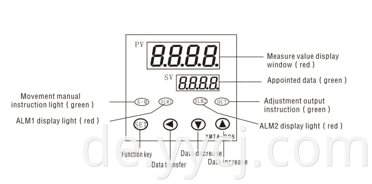
Ⅲ 、 Panel -Anweisung (Konsult)
Ⅳ 、 Code -Einstellungsmodus
|
Series
|
Code
|
Name
|
Setting range
|
Manual
|
Remarks
|
|
0
|
SP
|
Appointed data
|
Determined by P-SL P-SH
|
-
|
50.0
|
|
1
|
AL-1
|
Alarm 1
|
Determined by P-SL,P-SH when the upper and lower limit range,it is0~50.0 when the upper and lower limit deviation alarm
|
Alarm 1 setting value
|
10
|
|
2
|
AL-2
|
Alarm 2
|
Determined by P-SL,P-SH when the upper and lower limit range,it is0~50.0 when the upper and lower limit deviation alarm
|
Alarm 1 setting value
|
10
|
|
3
|
P
|
Proportion modulus
|
0~100
|
When the P↑,the the proportion function↓
When P=0,the meter is ON/OFF control
|
8
|
|
4
|
I
|
Calculus time
|
0~2000S
|
|
240
|
|
5
|
d
|
differential time
|
0~200S
|
|
30
|
|
6
|
At
|
Setting itself
|
ON:open setting inself function
OFF:close setting itself function
|
Select of setting itself
|
OFF
|
|
7
|
t
|
SSR proportion Control period
|
1~120S
|
the movements cycle ON/OFF of Setting relays control is no meaning
|
20
|
|
8
|
Hy
|
Main control by
drop in level
|
0.1~50.0
|
Only have meaning when main control output is ON/OFF(P=0)
|
1.0
|
|
9
|
Hy-1
|
Alarm 1
drop in level
|
0.1~50.0
|
It has use drop in level setting of alarm contact output
|
1.0
|
|
10
|
Hy-2
|
Alarm 2
drop in level
|
0.1~50.0
|
It has use dropin level setting of alarm contact output
|
1.0
|
|
11
|
Pb
|
Sensor error amendment
|
±20.0
|
The sensor have deviation can use item to revisal
|
0
|
|
12
|
FILT
|
Filt modulus
|
0~50
|
Is the software filter constants of measurement sampling.The constant ↑,the Measurements antijamming capabilityMeasurements antijamming capability↑,but the measurement and system time ↓
|
20
|
|
13
|
dp
|
Show accuracy
|
0~1
|
0: have radix point,1: have no radix point
|
-
|
|
14
|
P-SH
|
Display the high limit
|
P-SL~9999
|
Can set the high limit displaying input signal
|
400
|
|
15
|
P-SL
|
Display the low limit
|
-1999~P-SH
|
Can set the low limit displaying input signal
|
0
|
|
16
|
OUTL
|
Allow exports min value
|
0~OUTH
|
It will no role when highest outputlimit,,manual and position.
|
200.0
|
|
17
|
OUTH
|
Allow exports max value
|
OUTL~200
|
It will no role when lowest outputlimit,,manual and position.
|
0.0
|
|
18
|
ALP1
|
Alarm1 and output definition
|
0~4
|
‘0’:indicate no alarm
‘1’:upper limit touch alarm
‘2’:lower limit touch alarm
‘3’:upper windage alarm
‘4’:lower windage alarm
|
-
|
|
19
|
ALP2
|
Alarm2 and output definition
|
0~4
|
-
|
|
20
|
COOL
|
System function choice
|
0~1
|
‘0’:reverse control
‘1’:positive control
|
0
|
|
21
|
OPPO
|
Open power output
|
0~100
|
Soft start functionthat meters coefficient after first export of electric power
|
0
|
|
22
|
LOCK
|
Code lock
|
0~50
|
0- all the parameter can be revised
1- only the sp can be revised
|
0
|
|
23
|
Sn
|
Input type
|
0~70.
|
0-CU50 (-50.0~150.0℃) ;1-PT1 (-200.0~200.0℃) ;2-PT2 (-200.0~600.0℃) ;3-K (0~1300℃) ;4-E (0~700.0℃) ;5-J (0~900.0℃) ;6-T (-200~400.0℃) ;7-S (0~1600℃) ;
|
|
|
24
|
OP-A
|
Output type
|
1~4
|
1- RLP SSR output mode
2- SSR solid state relay
3- Zero controllable silicon contact signal when it exceed zero output mode
4- Mut controllable silicon phase trigger contact output mode
5- 0~10MA linearity control electric current output
6- 4~20MA linearity control electric current output
|
|
Ⅴ 、 technische Indizes
1 、 der erste Einstellbereich
Drücken Sie die Eingabetaste 3S in den ersten Einstellbereich. Das Messgerät zeigt den Parametercode 1 ~ 24in im Fenster in der oberen Zeile an und zeigt die Parameterdaten in der unteren Zeile an. In dieser Zeit drücken Sie die Taste ▲ 、 ▼ oder t, um den Parameter einzustellen, und drücken Sie dann die SET -Taste, um zu erhalten. Drücken Sie die Langzeittaste, die lange Zeit zurückzieht oder die SET + ƒ Taste direkt zurückzieht. Wenn nicht in 10 Sekunden jede Taste drücken, erhalten Sie automatisch die Daten und ziehen Sie die Einstellung zurück.
2 、 der zweite Einstellbereich
Wenn das Messgerät mit dem Strom eingerichtet ist, drücken Sie die festgelegte Taste in den zweiten Einstellbereich. Sie können das „SP“ entsprechend 1 festlegen.
3 、 Manuelle Regulierung
Wenn das Messgerät mit dem Strom eingerichtet ist, drücken Sie die T -T -Taste etwa 3s in die manuelle Verordnung. Es wird in dieser Zeit „H“ in der unteren Reihe angezeigt. In dieser Zeit kann die Ausgangsleistung einstellen. Drücken Sie die T -T -Taste etwa 3s erneut, es wird die manuelle Regulierung zurückziehen.
Ⅵ 、 、 sich selbst einstellen
Der Messgerät verwendet im ersten Mal oder in der Umgebung wechseln Sie, und findet es nicht gut. In dieser Zeit müssen Sie die Einstellung selbst verwenden. Zum Beispiel:
Der erste Satz der AT = ON, AM Light flackerte, das Messgerät in die Einstellung selbst in die Einstellung der SET -Taste in die Parametereinstellung eingereicht. Setzen Sie den Hy 0,5 ~ 1 ℃, wenn der Ausgang Relais eingestellt ist, das T = 2S ist, hat der Messgerät dreimal vibriert, automatisch erhaltene P, I, D -Parameter und das AT -Off, die Einstellung selbst.
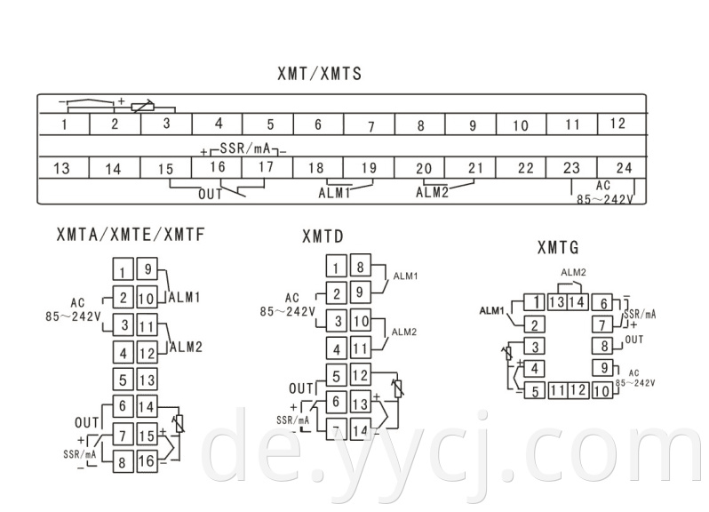
Ⅶ 、 Verbindungsschema (Konsult)
★ Bemerkung: Unser Unternehmen wird die Produkttechnologie verbessern. 、 Design und Spezifikation , Es ist dem Objekt bestätigt .。
Zurück: XMT-808 Series Universal Input Type Intelligenter Temperaturcontroller Weiter: FC-040 Einzeleingangstyp Intelligenter Temperaturcontroller